Display and operating elements

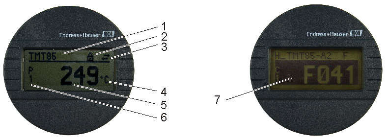
Optional the plug-on display TID10 can be used in connection with the head transmitter. Only if the display unit is used together with the head transmitter display and operating elements are available locally.

Display:

TID10 displays information regarding the current measured value and the measurement point identification. In the event of a fault in the measurement chain this will be displayed in inverse color showing the channel ident and diagnostics code. 


Item No. Function Description

1

Displays the TAG TAG, 32 characters long

2

"Configuration locked" symbol The "configuration locked" symbol appears when configuration is locked via
the hardware

3

"Communication" symbol The communication symbol appears when read and write accessing via the fieldbus protocol

4

Unit display

Unit display for the measured value displayed

5

Measured value display Displays the current measured value

6

Channel display e.g. C1 for a measured value from channel 1

7

Warning or error message If a warning occurs, the display alternates between the measured value and the warning code; if an error occurs the display alternates between the error code
and "- - - -" (no valid measured value available)


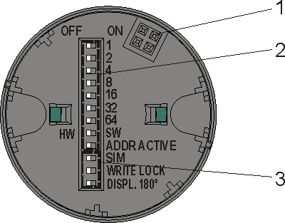
On-site operation

DIP switches can be found on the rear of the display TID10. These enable various hardware settings like for example the PROFIBUS®
device address..

Furthermore the DIP switches are used to enable and disable hardware write protection and to switch (turn) the display 180°. 
 

1

Connection to head transmitter

2

DIP switches (1 - 64, SW/HW and ADDR)


3


DIP switches (SIM = simulation mode; WRITE LOCK = write protection; DISPL. 180° = switch (turn) the display 180°)